
Investigation of hydrogen generation in subsea umbilicals
Development of a concept to prevent an explosive atmosphere in junction boxes
DOI: 10.60048/exm20_43Introduction
In the era of globalisation, subsea umbilicals are set to take on an important role. On the one hand, construction of oil and gas platforms is continuing, which requires subsea umbilicals for exchanging data and supplying cooling lubricants and electricity. On the other hand, the number of offshore wind farms is rapidly increasing at present, and will continue to do so in future, with subsea umbilicals being used to transport the power they produce to land. In a growing number of cases, a build-up of hydrogen has been detected in the junction boxes located above the surface of the water, where the subsea umbilicals are connected. Since the hydrogen does not escape by itself and instead builds up to form an explosive atmosphere in the junction boxes, an oil platform operator asked R. STAHL to explain possible reasons why this hydrogen was being produced and then to develop concepts to prevent an explosive atmosphere developing. These tasks were addressed in a Master's thesis completed at R. STAHL in Waldenburg in cooperation with R. STAHL Scandinavia in Oslo. The subject was the junction box for the electrical lines of a subsea umbilical. The difficulties encountered during the research were working out where in the cable the hydrogen is produced, and where it comes from, and also finding out how hydrogen moves in the cable and gets to the junction box.
")
Preliminary investigations and developing tests
Important points to look at during the preliminary investigation were the types of cables where hydrogen builds up, whether these cables were found to be damaged, the volume of hydrogen that leaks and where in the cable the hydrogen is located. The customer was only able to provide limited help with answering these questions. Other sources propose the theory that the hydrogen is produced due to corrosion of the galvanised steel in the cable [2]. It cannot be definitively established whether the cable needs to be damaged for this to happen, or whether this would also happen with undamaged galvanised steel, as we do not know how severe damage has to be for it to also be detected as damage to monitoring systems. However, hydrogen has been discovered in seemingly undamaged cables. Figure 1 illustrates the principle of anaerobic corrosion of two metals. The principle of a sacrificial anode is often encountered in shipbuilding, where it is used to protect the hull (more noble metal/cathode). The metals must be in direct contact with each other for electrons to flow.
The galvanised steel in subsea umbilicals is usually part of the outer sheath of the entire supply line, with the outermost insulating layer (generally HDPE or XLPE) being the only thing that separates it from water. The steel sheath increases the mechanical strength of the cable and is therefore used to protect it. However, this protection is sometimes omitted at depths of 0 m to 300 m to cut costs [8[3]].
The customer specified a hydrogen volume flow rate of one litre per day for the design of a usable solution. This value was confirmed to a limited extent by a report by Woodside [2], which ascertained a volume flow rate of 0.72 litres per day. However, this value was per conductor. The depth at which this cable was laid is not known, but its length of 23 km and voltage of 1000 V are similar to the values of the customer's cables. A poster by Shell [5] shows how a subsea umbilical expands in the shape of a balloon, as can be seen in figure 2. Once hydrogen was detected in the junction box, the balloons disappeared.

Another report [6] also assumes that all cavities in the cable fill up with water as early as during installation and that hydrogen starts to be produced immediately. Even if the cavities are not completely filled with water during installation, they will fill with water over time as HDPE is not watertight [7].
On the basis of this research, three different tests were prepared to investigate the behaviour of the cable or cable components in saltwater and under pressures of up to 20 bar. The first test looked at the water permeability of HDPE at 20 bar. This was followed by corrosion tests in which the samples were made of a combination of steel and zinc. In another test, the insulation was damaged in different ways, then it was transported through a pressurised container (20 bar) filled with saltwater and had a voltage of 600 VDC applied to it.
To design subsea umbilicals with sufficient resistance to water ingress or possible corrosion, cable manufacturers must cooperate with each other or guidelines need to be adapted. Until this happens and until hydrogen does not significantly damage components, another option is to prevent hydrogen turning into a hazard in the junction boxes. This has the added benefit of relatively simple installation, even when subsea umbilicals are already in place. A frequently mentioned option is attaching vent outlets to the junction box so that the hydrogen can escape. R. STAHL Tranberg in Stavanger was already involved in investigations in this field [8]. During these tests, vent outlets were attached to various points on the junction box but hydrogen did not escape fully in any of these tests. What's more, sensors at the top and bottom showed different hydrogen concentrations only during filling. Once the filling process was complete, the hydrogen was distributed evenly throughout the whole junction box in line with Dalton's law which states "each individual gas is distributed throughout the entire space as though no other gas were present."[9]. Active ventilation is not desirable, as this would entail increased maintenance which is associated with high costs, especially offshore.
Water permeability
In this test, a cable section which is also installed in subsea umbilicals was routed through an 8264 Ex d enclosure from R. STAHL, which was then completely filled with artificial seawater. The setup is shown in figure 3. 8174 cable glands were selected because these do not crimp the cable and can still withstand a pressure of 20 bar. This is important as if the cable gland crimps the cable, it will obstruct the water flow inside it. A glass vessel was placed at the bottom end of the cable, with the cable being routed through its lid and then adhered. This ensured that liquid could only enter the vessel through this cable. Then the connected pressure unit was used to build up pressure and keep it at this level for seven days. After the seven days, the pressure was released and the volume of liquid in the glass vessel was measured using a measuring cylinder. The volume of water measured in the vessel was 20 ml.

Corrosion tests on a combination of steel and zinc
For the corrosion tests, steel samples were fully coated using a zinc spray with a purity of 98%. A total of eight samples were prepared, which were then tested in pairs. Two of the samples were not damaged, an area of one square centimetre was scratched off two samples, two samples had two scratches 40 mm long, and two samples were damaged with four punch marks each. Following this, each sample was placed in a glass vessel filled with saltwater. The glass vessel was sealed with a lid. A compressed air hose ran through the lid from the glass vessel to a test tube. The test tube was sealed with a cork and placed upside down in water, as shown in figure 4, so that the only way for gas to get into the test tube was through the hose. The cork also had an additional hole to allow water to escape in the event of excess pressure in the test tube. The tests took place over 17 days in a climatic chamber at a temperature of 10 °C. Once the tests were complete, no change to the gas volume was detected. The hydrogen concentration was also measured using an X-AM 8000 measuring instrument from Dräger with an XXS-H2 sensor. The measuring instrument measured its limit value of 2000 ppm on seven of the eight samples, roughly corresponding to a concentration of 0.2 vol.%. This proved beyond doubt that hydrogen is generated in the course of anaerobic corrosion between steel and zinc in seawater.

Electrolysis tests
The test setup shown in figure 5 was used for the electrolysis tests. This is similar to the test setup for the water permeability test. In this test too, a pressurised enclosure was filled with seawater and then had pressure applied to it. The cable gland chosen was the A2F100 from CMP, as crimping of the cable does not affect the flow of current and therefore the time-consuming and complex step of moulding could be omitted. Firstly, pressure was applied and then a DC voltage source was connected to two of the four conductors for 30 minutes, which was able to provide a total voltage of 600 VDC. A total of five different cables were tested. The cables showed different signs of damage. One was not damaged, one had two 1 mm holes, with one hole extending to the red conductor and the other reaching the green conductor. One cable was pulled to 1000 N at both ends and one was wrapped around a 80 mm shaft far below the specified minimum bending radius, while a 0.6 mm needle was used to damage two points on the last cable, with the needle piercing through to the red conductor in one place and the green conductor at the other. On all cables, the insulation resistance between the green and red conductors was measured using a Fluke 1550B megohmmeter. At 20 bar, the insulation resistance only changed significantly at the hole and in the area which was damaged with the needle. The device's test voltage was 1000 VDC and it displayed a value of > 1 TOhm where the insulation was undamaged. The insulation resistance dropped to 6.75 kOhm at the hole and to 52.9 kOhm at the area which was damaged by the needle.

Gas movement in the cable
To test the movement of the gas in the cable, a gas cylinder with helium was connected to the bottom end of the cable. It was possible to constantly increase the pressure in this cylinder using a pressure reducing valve. Various connection options were tested at the top end, with only the test that was successful up to a test pressure of 10 bar being described here. The upper connection option is shown in figure 6. The additional enclosure, in which 15 mm of the cable is stripped, and the top end of the cable are fully covered in water so that any gas leakage is visible. The bottom cable glands only crimp the cable slightly, meaning that the gas volume flow rate is only minimally reduced. The top cable gland is an 8177 from R. STAHL which crimps the cable to such an extent that its diameter is decreased by 14%. The hose which is fitted to the additional enclosure is used to transport the escaping gas to a chosen safe area. Since still no gas leakage was visible at the top end of the cable at 10 bar, the test was ended and selected as the basis for a potential solution.

Potential solution
Since the previous test was successful and no gas leaked out of the top end of the cable, a first option was developed for transferring this to a cable and junction box. This involves inserting the cable into the first enclosure and removing the outer insulation. This allows the gas between the conductors and the outer insulating layer to escape safely, as there is no source of ignition in this area. Then the conductors are individually guided into the upper enclosure, where these are routed directly into additional small enclosures. Unlike in the tests, the small enclosures contain a terminal block to which the cable is connected. The cable is separated in this area, which further reduces the likelihood of gas escaping at the top end. What's more, the cable which extends from the main connection to the terminal blocks in the small enclosures and is crimped by the 8177 cable gland is already preassembled at the factory. However, the terminal block means that the voltage is limited for this suggested solution. Since terminal blocks are not considered sources of ignition and each conductor is inserted into a separate small enclosure, a build-up of hydrogen does not represent a hazard. The gas is transported from the small enclosure to a safe area via a hose outside the 8150 enclosure. The materials used for the tests were easy to obtain and adequate for allowing initial conclusions to be drawn. The approved zones or compatibility of the materials with hydrogen were not considered in this case.

What lies ahead
To be able to market the solution as a product, approved and suitable materials must be used and restested if necessary. The question of whether or not certification is needed must be clarified, as gas is only found in areas where there is no source of ignition.
The guidelines for subsea umbilicals also have to be adapted. Only materials that are saltwater-resistant should be approved, as there is water throughout the whole cable.
References
[1] R. Behrmann, „Investigation of hydrogen generation in subsea umbilicals and development of a concept to prevent an explosive atmosphere in junction boxes“, University of Applied Sciences, Trier, Waldenburg/Oslo, 2024.
[2] I. Robertson, „Electro-hydraulic Subsea Control Umbilical-Investigation of Gas Phenomena: Investigation of Gas Phenomena“, 16. August 2004.
[3] T. Worzyk, Submarine power cables: design, installation, repair, environmental aspects. Springer Science & Business Media, 2009. doi: 10.1007/978-3-642-01270-9.
[4] H.-J. Bargel und G. Schulze, Werkstoffkunde. Berlin, Heidelberg: Springer-Verlag, 2022. doi: 10.1007/978-3-662-63961-0.
[5] „EPE SHELL BRIEFING PAPER On THE SUBSEA CABLE ‚GASSING‘ PHENOMENON“, 1. September 2008.
[6] A. M. de Oliveira, „Hydrogen generation in umbilical: IOGP Electrical Standards Sub-committee (ESSC) 22nd/23rd October 2019 Workshop & Meeting“, 21. Oktober 2019.
[7] Goodfelllow, „PE-HD - Folie 0,01 mm dick 600 mm Rollenbreite“. Zugegriffen: 22. Januar 2024. [Online]. Verfügbar unter: www.goodfellow.com/de/p/et32-fm-000110/hdpe-film
[8] C. G. Gary Taylor Morten Dysjaland, „DC/FO - Hydrogen ventilation study (PJB): Test report“, 2. Juni 2023.
[9] C. Heinrich, „Technische Thermodynamik 2: Kapitel 9: Gasgesmische und feuchte Luft“.
More Article
Certification of Ex products
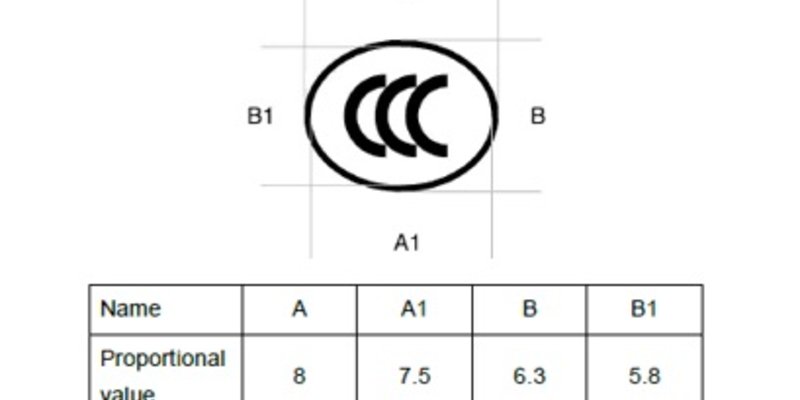
Since 1st October 2019, new CCC certification rules have been in place for Ex products sold in China
LNG - The key energy source in the medium-term on the way to…
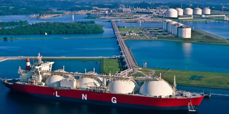
LNG stands for Liquefied Natural Gas and refers to natural gas that liquefies as it deep-cools to -162 °C and thereby shrinks to 1/600 of…
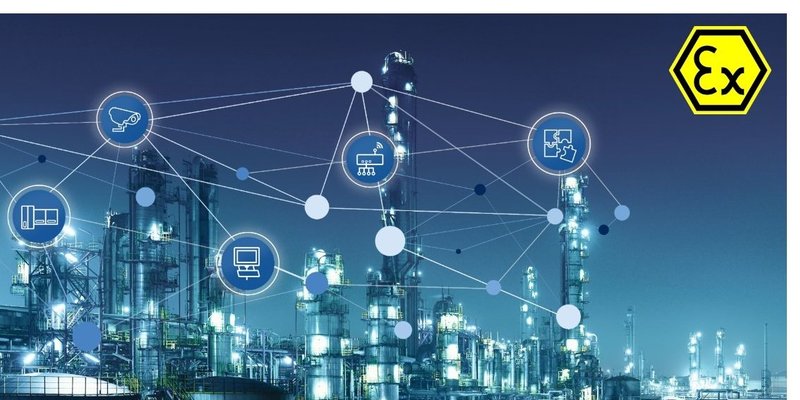
Competence and competencies in explosion protection
The field of explosion protection requires people who are able to respond competently, i.e. by choosing the correct course of action, in…
R. STAHL TRANBERG plays crucial role in world's first autonomous…
![[Translate to Englisch:]](/fileadmin/_processed_/2/8/csm_Yara_Bireland__Zero_Emission_d0e5ff95d4.jpg "[Translate to Englisch:]")
Remote control monitoring capabilities, situational awareness and resilience of R.STAHL TRANBERG’s navigation and search lighting key to…
The digital type plate in the era of Industry 4.0
![[Translate to Englisch:]](/fileadmin/_processed_/a/a/csm_Dig_Typenschild_Key_visual_quer_08c297ea4e.jpg "[Translate to Englisch:]")
A type plate contains essential information about a product, such as the manufacturer, product name and type, serial number and year of…
Power that never ends
![[Translate to Englisch:]](/fileadmin/_processed_/b/3/csm_Bild_13_USV_ADNOC_Offshore_Power_ohne_Ende_b07a7a5681.jpg "[Translate to Englisch:]")
Offshore platforms providing crude oil and natural gas require sufficient electrical energy in a continuous supply in order to guarantee…
Lithium-ion batteries for use in explosion protection
![[Translate to Englisch:]](/fileadmin/_processed_/b/c/csm_Lithium-Ionen_Akkus_Abbildung_7_3b0a489a32.png "[Translate to Englisch:]")
The advent of the digital revolution (industrial Internet of Things) has opened up new avenues for reducing costs and increasing system…
Explosion protection and digitalisation for automation
The digitalisation trend is showing no signs of slowing. The process automation sector is also working on this topic across a number of…