Lightning and surge protection in intrinsically safe measuring circuits
Risk assessment and implementation
Processing or transporting combustible substances can often lead to the creation of mixtures capable of forming an explosive atmosphere. Strict safety precautions must be in place when setting up and operating systems in which substances of this kind may be present. This is also set out in Directive 1999/92/EC [1], which addresses the user or employer. According to this directive, they are obliged to assess the explosion hazard posed by their system and they must ensure that all minimum regulations are complied with. Their tasks also include dividing the hazardous areas into zones, marking these areas and documenting all measures for protecting employees in the explosion protection document.
In Germany, European Directive 1999/92/EC [1] is implemented in national law by the Ordinance on Industrial Safety and Health (BetrSichV) [2] and by the Ordinance on Hazardous Substances (GefStoffV) [3]. The technical directives for industrial safety (TRBS) and for hazardous substances (TRGS) set out the corresponding regulations in more concrete terms. They provide users with information about the risk assessment and recommend protective measures for the corresponding sources of ignition.
The following article discusses lightning as a source of ignition in accordance with TRGS 723 [4].
Structure of the intrinsically safe system
An electrical circuit is considered to be intrinsically safe if the current and voltage are limited to such an extent that a spark or thermal effect cannot trigger the ignition of an explosive atmosphere. Unlike other types of protection (such as increased safety), this does not only relate to individual items of equipment, but to the entire electrical circuit. This applies to both normal operation and foreseeable cases of error (e.g. lightning strike). As a result, the entire intrinsically safe circuit must be protected against the intrusion of energy from sources outside the system. The constructor or user is responsible for proving the intrinsic safety and correct installation of the entire system.
Regulations DIN EN 60079 Part 11 [5], Part 14 [6] and Part 25 [7] govern the product features and special installation requirements. For instance, the intrinsic safety type of protection requires in all cases that cables or electrical lines are protected against mechanical damage, corrosion, and chemical and thermal effects.
As well as meeting the mechanical requirements, the intrusion of external energy into the intrinsically safe measuring circuit must be prevented. External energy can be coupled in galvanically, inductively or capacitively.

Risk assessment for Ex systems with "lightning strike" as a source of ignition
A risk assessment is performed in order to identify sources of ignition and to assess how they can become effective in the corresponding hazardous areas. A potential source of ignition may be a direct lightning strike, or the inductive and capacitive effects of this high pulse current on the intrinsically safe measuring circuit.
Point 5.8 of TRGS 723 [4] describes a "lightning strike" as a source of ignition. Here, the risk assessment relating to this source of ignition provides the following information:
- A lightning strike is an atmospheric discharge between a cloud and the ground. Extremely high temperatures arise at the point of impact. The high currents lead to increasing temperatures and potential shifts across the entire dissipation. The lightning current has electromagnetic effects (Image 1).
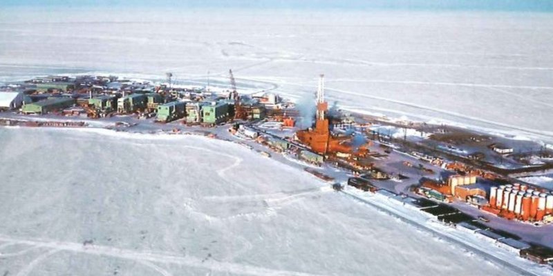
- A lightning strike can ignite an explosive atmosphere as a result of a direct strike, but also as a result of the effects of a strike a significant distance away (Image 4).
- If the lightning channel runs through an explosive atmosphere, such as a gas cloud, this will immediately be ignited. The high currents along the lightning's path can cause the parts of the system conducting the lightning current to heat up or can lead to corona discharges (Image 2).
")
The lightning channel penetrates into Ex Zone 1 and, if an explosive atmosphere is present at the same time, can lead to immediate ignition.
- Spark discharges or flashovers may occur due to the differences in potential between adjacent system parts.
- Currents and potential shifts are generated in metal parts in the environment around the discharge paths due to capacitive and inductive coupling (Image 3).

If the separation distance is not complied with, uncontrolled flashovers and disruptive discharges will occur from the discharge to the internal installation.
The dissipation of lightning currents generates strong electromagnetic influences (surges) in the metallic installation in the building or system.

- The effects that lightning strikes occurring at a significant distance can have on supply lines (cables and conduits) must be taken into account insofar as they can cause repercussions in the hazardous area (Image 4).
Sources of damage S3 and S4 (Table 2) in accordance with DIN EN 62305-2 [8] describe the direct and indirect influences that lightning can have on all routed-in metallic conductors.
These can carry high amounts of ignition energy into the hazardous area from far away.
- The risk assessment must evaluate ignition hazards due to lightning strikes for hazardous areas as a whole.
 in accordance with DIN EN 62305-1 [8]")
In hazardous areas, therefore, a risk is posed not only by the effects of a direct lightning strike, but also by the electromagnetic effect of the lightning current on the installation of the electrical system and metallic installations (e.g. cables). If an explosive atmosphere is present at the same time (e.g. at the connection terminals in the enclosure of an intrinsically safe item of equipment), the ignition energy that is released by a flashover can lead to a fire or explosion at any time.
For this reason, it is extremely important in terms of the safety of the entire system to ensure that an enclosed, coordinated, very detailed protection concept is implemented. DIN EN 62305-4 [8] refers to the "lightning protection zone" concept and forms the basis for the structure of a lightning protection system in a hazardous area. Cables and conductors are particularly at risk due to the inductive effect of the lightning current. Intrinsically safe measuring circuits are often found in hazardous areas. While Section 12.3 of the standard DIN EN 60079-14 [6] lists requirements for lightning protection for intrinsically safe circuits, DIN EN 62305-4 [8] presents the state of the art for controlling surges in a system at risk of explosion.
Coupled-in partial lightning currents and induced surges in the intrinsically safe system
The process now involves assessing the hazards to the intrinsically safe system within the plant, as described in TRGS 723 [4], to determine whether hazardous consequences due to the effects of lightning may result (Images 5a to 5d) from one of the sources of damage (Table 2). This is a very complex matter and can only be assessed in its entirety by experts (lightning protection specialists or EMC experts with knowledge of systems with hazardous areas). The risk assessment in accordance with DIN EN 62305-2 [8] offers additional assistance.


 with spark formation at the point of impact and flashovers to the electrical installation")

If hazards due to the effects of lightning (TRGS 723 [4] accompanied by the risk assessment in accordance with DIN EN 62305-2 [8]) are identified, all devices, protection systems and components in all categories must be protected using suitable lightning and surge protection measures. It is extremely important in this respect to ensure that lightning strikes outside Ex Zones 0/1 or 20/21 do not have any harmful effects on these zones.
Installation requirements related to atmospheric discharges (lightning strike)
On the subject of lightning hazards, DIN EN 60079-14 [6] refers directly to measures corresponding to the DIN EN 62305-1 to -4 series of standards [8].
The overall concept for planning lightning protection systems in hazardous areas comprehensively takes into consideration:
- Determining the point of impact using the lightning sphere method (R = 30 m as per TRGS 723 [4]) and assessing whether the corresponding points of impact could lead to hazardous couplings in the hazardous area
- Constructing an external lightning protection system with an LPL of at least II, consisting of interception systems, dissipation systems, an earthing system, lightning protection equipotential bonding and a separation distance
- Depicting the lightning protection zones, as well as the Ex zones, in drawings (ideally using a 3D drawing tool such as DEHNplan)
- Evaluating the electromagnetic coupling of the external lightning protection system in conductor loops (intrinsically safe measuring circuits including open cable shields) using DIN EN 62305-4 [8]
- Implementing protection measures to counteract the effect of the lightning electromagnetic pulse (LEMP) using an LEMP protection system (LPMS). A unique combination of these LEMP protection measures includes earthing, equipotential bonding, spatial shielding, cable routing and shielding, and coordinated SPD protection
The following case study (Image 6) shows an example of this. Below, it is assumed that a lightning protection system (LPS) with lightning protection class II has been constructed in order to provide protection against direct strikes in the intrinsically safe system and in the hazardous areas (Zone 0, 1); it is assumed that this protection class is based on the corresponding hazard level LPL II from a previous risk assessment. The intrinsically safe measuring circuit is installed in lightning protection zone (LPZ) 0B (see Table 1).

The example explains one possible method of protecting intrinsically safe measuring circuits against the direct and indirect effects of a lightning strike.
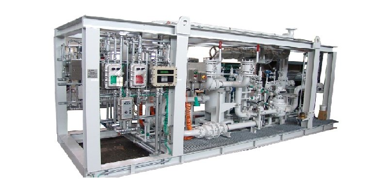
Image 6 shows one typical way of installing an intrinsically safe measuring circuit, consisting of a combination of an associated electrical apparatus (isolator from the ISpac series), intrinsically safe cable installation, a temperature transmitter (galvanically separated from the sensor element), and the corresponding required surge protection devices (SPDs). The isolator is in the I&C (instrumentation and control) cabinet in the control room (non-hazardous area). The temperature transmitter with the sensor element is installed directly on the tank containing the combustible liquid. The sensor element is positioned directly in Ex Zone 0. The transmitter itself is installed in Ex Zone 1 and is connected directly, safely and permanently to the metallic tank using its metal enclosure. The shielded, intrinsically safe cable (approx. 200 m long) connects the two items of equipment. The measuring station and tanks are both integrated in a meshed earthing system (mesh width approx. 20 x 20 m).
In order to implement protection against all lightning-related risks of damage to the electrical equipment (control room and in the hazardous area), two SPDs must be integrated in the intrinsically safe circuit. One SPD protects the isolator in the control room and the other SPD protects the transmitter on the tank. At the same time, the SPD on the tank also prevents any hazardous spark discharge from the tank to the sensor conductor, as well as providing explosion protection. The SPDs mean that the signal wires, the unused wires and the open cable shields are all connected to the circuit. As a result, no compensating current can flow in normal operation. If hazardous surges occur, the open cable ends are connected to the equipotential bonding via the SPD, thereby preventing any sparks from being created in the open.
Required criteria for the use of SPDs in the intrinsically safe measuring circuit
In order to guarantee the protective effect of the SPD as well, the installation conditions set out by the manufacturer and the additional installation conditions set out in the EC Type Examination Certificate must be met. Intrinsically safe measuring circuits, in particular, have unique characteristics in this respect. These must always be taken into consideration when installing the SPDs, as other wise the intrinsic safety could be impaired.
Taking into consideration the standard DIN EN 60079-25 [7], intrinsically safe circuits may either be "insulated from earth" or only "connected to the equipotential bonding system at one point". An intrinsically safe circuit is considered to be floating if it is able to withstand an insulation test with at least 500 V against earth, in accordance with DIN EN 60079-11 [5].
When using intrinsically safe systems that are designed to be floating, only SPDs that are able to withstand an electric strength of 500 V against earth may be used. The manufacturer of the intrinsically safe SPDs must provide proof that they are floating.

Since a sensor conductor with SPD must be connected on the tank (Images 6 and 8) and must be routed into Zone 0, the SPD must additionally be approved for this usage (conductors from Ex Zone 0). According to the EC Type Examination Certificate, the SPD of type DPI MD EX 24 M2 or type BCO ML2 BD EX 24 in our case study must have the following approval:
II (1)2 G Ex ia [ia Ga] IIC T4 ... T6 Gb
Since the surge protection devices are integrated directly into the intrinsically safe measuring circuit, all interconnection conditions set out in DIN EN 60079-14 [6] must, of course, also be met. These include
| Associated electrical apparatus | Condition | Intrinsically safe measuring circuit | Typical values for SPDs made by DEHN, type BCO ML 2 BD EX 24 |
|---|---|---|---|
| Maximum output voltage U0 [V] | ≤ | Maximum input voltage Ui [V] | 30 V |
| Maximum output current I0 [mA] | ≤ | Maximum input current Ii [mA] | 500 mA |
| Maximum output power P0 [mW] | ≤ | Maximum input power Pi [mW] | 2000 |
| Maximum external inductance L0 [mH] | ≥ | Sum of all maximum internal inductances (Li + Lc) [mH] | 0 mH (negligible) |
| Maximum external capacitance C0 [nF] | ≥ | Sum of all maximum internal capacitances (Ci + Cc) [nF] | 0 nF (negligible) |


Minimum discharge capacity of surge protection devices
When installing an SPD on the tank (often conductors from Zone 0), in particular, the following requirements as set out in DIN EN 60079-14 [6] must be met and verified:
Use of SPDs with a minimum discharge capacity of 10 pulses each of 10 kA (8/20 µs) without any defects or impairment of the protective function.
Note:
In many applications, however, the SPDs must be able to discharge galvanically and inductively coupled surges. For this reason, we recommend using surge protection devices that are tested with a lightning pulse with a wave form of 10/350 µs (galvanic coupling) and wave form 8/20 µs (induced coupling). These offer a higher degree of safety, as well as making selection and recurring inspections easier.Installation of the SPDs in a metallically shielded enclosure and earthing with at least 4 mm² Cu.
Installation of the conductors between the dissipation system and equipment in a metal conduit that is earthed on both sides, or use of shielded conductors with a maximum length of 1 m.
In the case study we have described (Image 6), all these points have already been fulfilled through the use of the field device protection type DPI MD EX 24 M2.
Summary
The hazard to chemical and petrochemical systems posed by a lightning discharge and the resulting electromagnetic influences is often not assessed in its entirety in practice, even though this has been required according to TRGS 723 [4] since July 2019. When implementing the lightning protection zone concept, when taking hazardous areas into account during the planning and execution stages, the risks of sparks forming due to a direct strike or discharged grid-bound and induced interference energy can be reduced to a viable extent from a safety-related and economic perspective. The SPDs used must fulfil the requirements in terms of explosion protection, coordination conditions, and the requirements resulting from the operating parameters of the I&C (instrumentation and control) circuits.
References
[1] Directive 1999/92/EC of the European Parliament and of the Council of 16th December 1999 on minimum requirements for improving the
safety and health protection of workers potentially at risk from explosive atmospheres.
[2] German Ordinance on Industrial Safety and Health (BetrSichV), as at 03.02.2015 Regulation on safety and health protection when using
work equipment
[3] Ordinance on Hazardous Materials (GefStoffV), as at 26.11.2010 Regulation on protection from hazardous substances
[4] TRGS 723 – Hazardous explosive mixtures – Avoidance of the ignition of hazardous explosive mixtures (Edition: July 2019)
[5] DIN EN 60079-11 (VDE 0170-7): 2012; Explosive atmospheres - Part 11: Equipment protection by intrinsic safety "i"
[6] DIN EN 60079-14 (VDE 0165-1): 2014; Explosive atmospheres - Part 14: Electrical installations design, selection and erection
[7] DIN EN 60079-25 (VDE 0170-10-1): 2011; Explosive atmospheres - Part 14: Electrical installations design, selection and erection
[8] DIN EN 62305-1 (VDE 0185-305-1): 2012; Protection against lightning -
Part 1: General principles
Part 2: Risk management
Part 3: Physical damage to structures and life hazard
Part 4: Electrical and electronic systems within structures
Abbreviations used
SPD: Surge protective device
TRBS: Technical rules for industrial safety
TRGS: Technical regulations on hazardous substances
LPZ: Lightning protection zone
LPS: Lightning protection system
LEMP: Lightning electromagnetic pulse
LPMS: Lightning protection measures system
LPL: Lightning protection level
Li: Total of all maximum internal inductances of the intrinsically safe equipment used
Ci: Total of all maximum internal capacitances of the intrinsically safe equipment used
More Article
Investigation of hydrogen generation in subsea umbilicals

In a growing number of cases, a build-up of hydrogen has been detected in the junction boxes located above the surface of the water, where…
Ex in sight
![[Translate to Englisch:]](/fileadmin/user_upload/magazin/artikel/20_27_Ex_im_Blick/1_Ex_im_Blick_Teaser.jpg "[Translate to Englisch:]")
Incorrect storage of hazardous chemical substances and inadequate surveillance of storage areas all too often result in catastrophic…
The Need for Integrated Project Management

Reducing project management and development time alone has the potential to deliver 15 to 30 percent in cost savings
Static and dynamic material stresses acting on Ex "d" enclosures
Flameproof enclosures must be subjected to certain testing, including of their ability to withstand pressure
PLP NZ celebrating 45 years with R. STAHL

45 years ago, three things came together, R. STAHL, PLP (Electropar Ltd), and the willingness to adopt innovative new hazardous area…
Emergency lighting
Central battery systems as emergency lighting systems offer secure protection in the event of a power supply failure
Sensing nonsense: When appearances are deceptive
Process engineering systems are generally controlled by measuring process variables such as temperature, pressure, quantity, fill level or…
Digital support for visual inspections using deep learning

The use of deep learning models offers huge potential for reducing the error rate in visual inspections. Smart object recognition enables…
Lightning and surge protection in intrinsically safe measuring…

According to Directive 1999/92/EC [1], the user or employer are obliged to assess the explosion hazard posed by their system and they must…
Ex assemblies, Part 1

The discussion about Ex assemblies is as old as the EU ATEX Directive, and now dates back almost 20 years
How R. STAHL TRANBERG is Meeting the Digitalization Demands of…

Digitalization and the integration of data and solutions is playing a pivotal role in the shipping and maritime industries today, having a…
The "PTB Ex proficiency testing scheme"

The "PTB Ex proficiency testing scheme" (PTB Ex PTS) is a project that involves developing interlaboratory comparison programmes to assess…
Non-electrical explosion protection
Manufacturers and users must acquire knowledge on the subject of non-electrical explosion protection, in order to assess the application,…
Certification in South Africa

Certification in South Africa has certain key differences from international certification, e.g. IECEx or ATEX
Global conformity assessment using the IECEx system
![[Translate to Englisch:]](/fileadmin/_processed_/c/e/csm_Einstiegsbild_IECEx_Paragraf_38414b50d0.jpg "[Translate to Englisch:]")
IEC Technical Committee (TC) 31, tasked with developing a global conformity assessment system for explosion-protected products
A mine of experience in industry
![[Translate to Englisch:]](/fileadmin/_processed_/f/f/csm_Einstiegsbild_e_tech_IEC_6270d7c66a.jpg "[Translate to Englisch:]")
He takes over from Thorsten Arnhold, who chaired the System for the past six years
Conformity assessment in the USA
In contrast to the international IEC/IECEx community and the European Union, the conformity assessment landscape in the USA is very…
25 Years of the Zone System in the USA
In the area of explosion protection, the publication of Article 505 in the 1996 National Electrical Code (NEC®) was seen as a giant step…
An Ex-citing future with hydrogen
![[Translate to Englisch:]](/fileadmin/_processed_/0/1/csm_shutterstock_1644506059_7d60f29da8.jpg "[Translate to Englisch:]")
Aside from a few exceptions based on the effect of gravitation and radioactivity, hydrogen is the source of most primary energy that makes…
Certification of Ex products
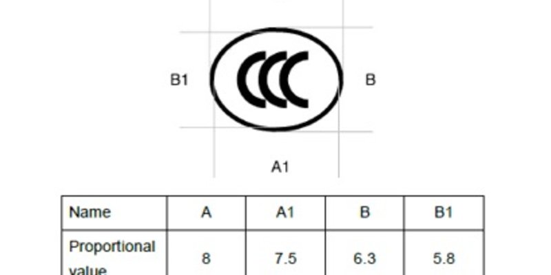
Since 1st October 2019, new CCC certification rules have been in place for Ex products sold in China