
Explosion protection and digitalisation for automation
DOI: 10.60048/exm20_15The digitalisation trend is showing no signs of slowing. The process automation sector is also working on this topic across a number of levels. New abbreviations such as NOA (NAMUR Open Architecture), OPAF (Open Process Automation™ Forum) and MTP (Module Type Package) regularly appear in almost all the latest specialist publications. However, unlike industrial automation, this involves an additional hurdle to overcome – the hazardous areas that are present in many systems in chemical, pharmaceutical or oil and gas companies. In particular, IP communication down to the field level plays an important role in these sectors and in new concepts. NAMUR recommendation NE168 "Requirements for an Ethernet communication system for the field level" therefore also requires "suitable explosion protection" for "Ethernet in the field" solutions of this type. In the past, the "intrinsic safety" type of protection in accordance with DIN EN 60079-11 has been tried and tested to great success in these sectors and is well-established around the world. However, depending on the application and requirements, entirely different solutions may be practical options.
Here, we will take a closer look at the different concepts and their relationship with explosion protection, with a particular focus on the topic of "Ethernet in the field".

The country needs new concepts – NOA, OPA, MTP
The idea of the automation pyramid as a basis for architecture in process engineering has long been obsolete, but more and more people are returning to its fundamental ideas. The NAMUR Open Architecture (NOA) project is based on the classic pyramid shape from the past, but has expanded it to include additional functions. This approach is ideally suited for system expansions (brownfield work) in particular, but is also suitable for new systems (greenfield). This expansion, which is also known as a "second channel", primarily serves to make additional information from process and field devices available for use. The second channel can either be set up as additional infrastructure or can make use of the existing infrastructure – whichever is more effective. This structure can be set up relatively easily, especially in modern Remote I/O systems with Ethernet connectivity. With the right certified products, it can even be set up in hazardous areas up to Zone 1. The network connection is then established via either explosion-protected fibre optics or intrinsically safe Ethernet – we'll discuss that in more detail later. In existing systems, a Remote I/O system continues to communicate, for instance using the classic PROFIBUS DP to communicate with the control system. An Ethernet network is connected in parallel as a second channel and used for enhanced diagnostics and for HART data transmission. If the control system is retrofitted, e.g. for PROFINET, this ensures that the required Ethernet infrastructure is already present and the process bus is converted to PROFINET communication, thereby becoming just another network for process data, diagnostics and HART information. In the past, this additional data could be accessed by engineering stations or cloud systems using an integrated web server or FDT/DTM. Since then, however, solutions based on OPC UA have become available and even the state-of-the-art FDI (Field Device Integration) technology is intended to be available for use for Remote I/Os using a new working group in the near future.
Over the course of the work being done on NAMUR Open Architecture, the open standard OPC UA (Open Platform Communications Unified Architecture) has become increasingly important for data exchange thanks to its manufacturer- and platform-independent nature. OPC UA does not transmit data from devices or machines, like many other protocols already do – it is capable of describing this data for machines in a comprehensible form, otherwise known as semantics. To achieve this, corresponding information models are required for each device and machine. These are described in OPC UA in the "companion specifications". While there are already many companion specifications for industrial applications such as robotics, less attention has been paid to the field of process automation in this context. In 2017, the FieldComm Group (FCG) and the OPC Foundation, with later support from NAMUR and PROFIBUS/PROFINET International, began establishing specifications for a Process Automation Device Information Model, or PA-DIM for short; Version 1.0 was published in June 2020. This enables, for instance, a Remote I/O to read out information from connected typical HART field devices, translate it for the PA-DIM, and make it available to other systems and the cloud via Ethernet and OPC UA. However, the required specifications for standardised translation from HART to PA-DIM are yet to be provided – but this is merely a question of time.
The Open Process Automation™ forum has gone one step further. Here, the classic pyramid has been abandoned in favour of decentralised structures. The process control level, control level and parts of the field level, such as Remote I/Os, wireless gateways or analysis devices, are connected to each other on a single level via a real-time bus, which can itself be based on Ethernet with OPC UA. OPAF places particular emphasis on consistent interoperability between different manufacturers, all the way to complete component interchangeability. This unmistakably revolutionary approach will need some time yet before it can be implemented practically, particularly when we consider critical installations in hazardous areas and high availability requirements. In this respect, the fundamental elements of basic technology for explosion protection via intrinsically safe Ethernet or explosion-protected Remote I/O systems, for instance, are already available.
A more advanced concept is the concept of modular automation, which has become part of considerations in NOA and OPAF. The basic idea is that recurring applications, machines or package units will only need to be planned once; they can then be linked into the process landscape as modules using a standard interface. This achieves significant savings during planning and commissioning, as well as by ensuring that solutions of this type are reusable. The heart of this concept is the standardised Module Type Package (MTP), which describes the features and interfaces of a module. As well as these descriptions, which can almost be considered the device drivers, the physical interfaces must match. Ethernet, as well as the closely linked concept of IP communication, has once again proven to be an ideal basis for creating open, interoperable solutions. Accordingly, we are once again faced with the question of how this can be implemented in hazardous areas.
Ethernet – the common denominator in digitalisation
The requirement for a digital infrastructure in process industry systems is no new phenomenon. Some of us may remember the "fieldbus wars" of the 1990s, during which a number of fieldbus solutions fought to win users' favour. However, the solutions that resulted, which are still in use today, do not meet all current user requirements and do not appear capable of offering a future-oriented solution for the digital production systems of the future. Ethernet – or, more accurately, the resulting opportunity for system-wide IP communication from the field level to the control system and beyond – provides better conditions for this purpose and is a suitable basis for solutions. The continuous further development of Ethernet technology, such as higher data rates or improved real-time capability, as well as the globally installed foundations for this technology and the quantity of available Ethernet components and tools, reinforce its future sustainability. However, the process industry also faces wider-reaching requirements. Long system service lives and the resulting long-term use of the distributed control systems, field devices and associated infrastructure, as well as strict demands regarding safety, security and availability, pose particular challenges for digital and networked communication systems. Not least, these include the requirement for easy-to-use explosion protection – in this respect, the "i" intrinsically safe type of protection (DIN EN 60079-11) is of particular interest.

Company-specific, proprietary implementations of intrinsically safe Ethernet have existed for years. However, these are not compatible with one another, nor do they meet the established global IEEE standards. As a result, we will not discuss these specific solutions in this article. As an alternative, for instance, Remote I/O systems and HMIs in combination with Ethernet have been installed in hazardous areas with fibre optics for more than ten years. In particular, the "op is" type of protection for optical radiation, based on intrinsic safety (optically inherently safe, DIN EN 60079-28 "Explosive atmospheres – Part 28: Protection of equipment and transmission systems using optical radiation") combines this flexible explosion protection with large distances of up to 30 km and excellent immunity. However, there are many applications in which fibre optics are unacceptable for structural reasons or cannot be used for functional reasons, for instance if the power supply also needs to be provided via the cable, as is typically the case for fieldbuses in process automation.
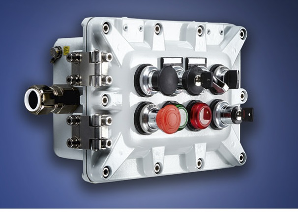
In principle, Ethernet cables can also be routed into hazardous areas in accordance with the increased safety "e" type of protection (IEC 60079-7), or as fibre optics in accordance with "op pr" (protected routing according to IEC 60079-28). This is based on a combination of electromechanical protection measures that prevent explosive atmospheres from being ignited by sparks, heat or optical energy. In order to prevent damage and therefore eliminate potential sources of ignition, particular attention must be paid here to the suitability of the cables and their conduits. Conventional RJ45 connectors are unsuitable for use in Zone 1; certified Zone 1 Ethernet terminals are used. Modifications or maintenance work in hazardous areas are, however, only possible to a limited extent when these types of protection are used. In normal circumstances, they require the systems to be switched off.
How Ethernet became intrinsically safe – Ethernet-APL and 100 BASE-TX-IS
Intrinsic safety is a type of protection based on the fact that a defined amount of energy is required in order to ignite a certain explosive atmosphere. To prevent ignition, the amount of energy in an intrinsically safe circuit is therefore reduced to a safe level by limiting the current and voltage accordingly. For intrinsically safe circuits and devices, therefore, required work such as extensions, modifications or repairs on live equipment (hot work), or adding and disconnecting devices (hot swap) can be performed within hazardous areas without needing to completely switch off systems or system parts. The required computational detection methods for the intrinsically safe installation and the restriction of the available energy to approx. 2 watts are often seen as disadvantages. These aspects also play a significant role in the development of intrinsically safe Ethernet.
Various Ex i Ethernet approaches have failed in the past as a result of insufficient interoperability or compatibility with international standards, such as the IEEE standards.
To meet the user requirements, such as those set out by NAMUR in NE 168, for interoperable, intrinsically safe, easy-to-use Ethernet, a number of manufacturers put their heads together some years ago. Two working groups, the Advanced Physical Layer (APL) project and the Intrinsically Safe Ethernet Working Group, are working on developing solutions for standardised intrinsically safe Ethernet for two different applications.
Ethernet-APL is the dedicated solution for the use of Ex i 2-conductor field devices in process automation. This technology is based on the Physical Layer of Single Pair Ethernet (SPE) 10BASE-T1L in accordance with the relatively new IEEE Std 802.3cg-2019 specification. SPE was designed to bridge distances of up to 1000 m on 2-wire conductors at 10 Mbit/s, while simultaneously offering an optional power supply for connected devices (Power over Date Lines, PoDL).
Ethernet-APL is compatible with most features of SPA but uses a supply concept that differs from PoDL for field devices, in order to enable the use of the intrinsic safety type of protection. Other plug connectors and priority clamping connections can also be used, since Ethernet-APL prioritises use in the field in process automation.
The APL project places particular emphasis on the development of an intrinsically safe extension for SPE for use in hazardous areas in Zones 0 and 1 and for NEC installations in DIV 1 and 2 as well. In line with the Ex i system concept for fieldbuses, FISCO (fieldbus intrinsically safe concept), the 2-WISE (2-wire intrinsically safe Ethernet) concept has been developed in collaboration with DEKRA EXAM, so that Ethernet equipment from different manufacturers can be interconnected easily and without the need for intrinsic safety verification computations. Cable parameters therefore do not need to be considered further within the context of the specified Ethernet-APL parameters. Like FISCO, 2-WISE is based on IEC 60079-25 "Intrinsically safe systems" and simplifies planning and Ex i verification significantly. In order to make the migration of existing fieldbus installations as simple as possible, 2-WISE has the same Ex i parameters as those specified in FISCO; additionally, fieldbus "type A" cables can be used. The fundamental difference between them is that Ethernet-APL has a significantly higher data rate of 10 Mbit/s, compared to the FISCO field bus data rate of 31.25 kBit/s.
The 2-WISE concept is intended to be published in March 2021 as a technical specification in IEC TS 60079-47 "Equipment protection by 2-Wire Intrinsically Safe Ethernet concept (2-WISE)".
Of course, Ethernet-APL networks can also be installed in hazardous areas with other types of protection, such as increased safety "e" or flameproof enclosure "d", in which case it does not have the convenient "hot swap" or "hot work" intrinsic safety characteristics.

As well as being a practical solution for explosion protection, Ethernet-APL also offers other advantages. Typically, up to 50 field devices in a network can be supplied from a central system power supply that provides approx. 90 W. Ethernet-APL enables the use of a number of installation concepts. A typical structure for installations in hazardous areas can be derived from classic fieldbus technology. The APL power switch supplies the Ethernet network with power over a maximum distance of 1000 m. APL field switches that convert the energy supplied via this trunk into intrinsically safe energy and distribute this energy to outputs, otherwise known as spurs, are installed in the field – i.e. in Zone 1 or Zone 2. The field devices are operated and supplied with power at the Ex i spurs, which can be up to 200 m long. Depending on whether the spurs are designed as ia, ib or ic electrical circuits, they are installed in Zone 0, 1 or 2.
As well as the supply to the field switches via the trunk, as described above, externally supplied field switches can also be used as an alternative. Typically, these then communicate using a standard Ethernet backbone, e.g. 100BASE-TX or -FX and can be integrated into ring structures. The combination of different Ethernet technologies and topologies results in a variety of potential uses and applications.
As well as manufacturers, four Standard Development Organisations (SDOs) for industrial communication are also involved: FieldComm Group (FCG), ODVA, OPC Foundation and PROFIBUS+PROFINET International (PI). On one hand, the SDOs ensure that Ethernet-APL is compatible with the corresponding communication protocols, i.e. with HART-IP (FCG), EtherNet/IP (ODVA), OPC UA (OPC Foundation) and PROFINET (PI). On the other hand, they ensure that the technology developed by their member companies is adapted and distributed.
100BASE-TX-IS was developed as a specification for devices that require higher bandwidths and more energy than is currently available with Ethernet-APL. It focuses on complex field devices, analysis devices, operating terminals and Remote I/O systems. The "Intrinsically Safe Ethernet Working Group" expands the published 100BASE-TX Ethernet in accordance with IEEE 802.3 to include an intrinsically safe front end. This means that 4-wire Ethernet with data rates of up to 100 Mbit/s is available in an intrinsically safe version and is therefore fully interoperable with the industry standard. The core electronics of devices with IEEE 802.3u-compliant MAC (Media Access Control) and 100BASE-TX PHY (Physical Layer) is maintained and expanded to include Ex i switching. If applicable, additional galvanic separation from the power supply may be required.
In this case, similar to Ethernet-APL, no laborious proof of intrinsic safety is required – a simple comparison of the 100BASE-TX-IS-compliant participants is sufficient. Since the ancillary parameters of a 100BASE-TX-IS installation are always known – exactly two point-to-point participants (and therefore exactly two energy sources) connected via no more than 100 metres of CAT 5/6/7 cables – generally accepted proof of intrinsic safety can be obtained on the basis of IEC 60079-25 "Intrinsically safe electrical systems". For exemplary purposes, this has been performed and documented by the PTB using the ISpark tool. This means that the planner does not have to perform any additional calculations and limits proof of intrinsic safety to the documentation of the participants and their interconnections.
In contrast to Ethernet-APL, 100BASE-TX-IS provides no integrated power supply and therefore no "Ex i Power over Ex i Ethernet". Like the underlying 100BASE-TX standard, it enables distances of max. 100 m to be covered using CAT cables. It can therefore be assumed that manufacturers will bring corresponding 100BASE-TX-IS switches and media converters with additional FO interfaces, e.g. with "op is" type of protection, to the market. These will allow significantly greater distances to be bridged through to Zone 1 – when single mode fibres are used, these distances can span 30 km or more.
What are you waiting for?
Of course, Ethernet-APL and 100BASE-TX-IS are designed to be perfectly combinable in systems – when it comes to communication, these solutions are transparent and thereby support protocols such as Ethernet/IP, PROFINET or HART-IP, and OPC UA equally. 100BASE-TX-IS allows devices that require higher bandwidths, e.g. Remote I/O systems, to be operated jointly with new, intelligent Ethernet-APL field devices within a network in hazardous areas in Zones 1 and 2. While intrinsically safe 2-wire Ethernet field devices are connected via field switches, these field switches are connected to other participants such as Remote I/O systems and the control system using, for instance, an intrinsically safe 100BASE-TX-IS backbone. Consistent IP communication from the control centre to the field – the goal which all digitalisation work in process automation is striving to achieve is within our grasp.

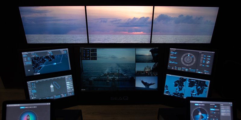
Alongside the somewhat more distant scenarios such as NOA, NTP or OPA, applications for Ethernet in hazardous areas already exist. In Zones 1 and 2, operating and monitoring systems can be operated as thin clients in an Ethernet network using "op is" fibre optics, for example. Applications such as SoftPLC and SCADA can therefore also be used in hazardous areas because fast Ethernet makes integration into the existing infrastructure incredibly easy. CCTV IP cameras for monitoring systems and processes are also available in explosion-protected versions for consistent IP communication.
Many field devices can already be integrated via Ethernet, even if they do not have a corresponding interface themselves. Most control systems support a range of Ethernet protocols and, thanks to state-of-the-art Remote I/O systems, the option to implement Ethernet communication via PROFINET, Ethernet/IP or Modbus TCP in hazardous areas in Zone 1 has been available for a long time. Even HART information from field devices is transmitted transparently in this process; currently, this information can be processed using FDT/DTM technology or OPC UA independently of the process bus in the asset management systems. Explosion protection and digitalisation are ready to take on the challenges that automation will bring.
More Article
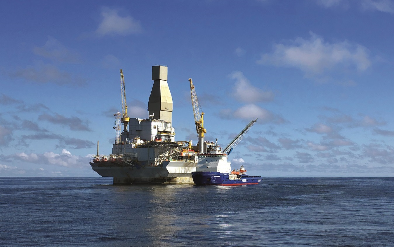
Investigation of hydrogen generation in subsea umbilicals

In a growing number of cases, a build-up of hydrogen has been detected in the junction boxes located above the surface of the water, where…
Ex in sight
![[Translate to Englisch:]](/fileadmin/user_upload/magazin/artikel/20_27_Ex_im_Blick/1_Ex_im_Blick_Teaser.jpg "[Translate to Englisch:]")
Incorrect storage of hazardous chemical substances and inadequate surveillance of storage areas all too often result in catastrophic…
The Need for Integrated Project Management
Reducing project management and development time alone has the potential to deliver 15 to 30 percent in cost savings
Static and dynamic material stresses acting on Ex "d" enclosures
Flameproof enclosures must be subjected to certain testing, including of their ability to withstand pressure
PLP NZ celebrating 45 years with R. STAHL

45 years ago, three things came together, R. STAHL, PLP (Electropar Ltd), and the willingness to adopt innovative new hazardous area…
Emergency lighting
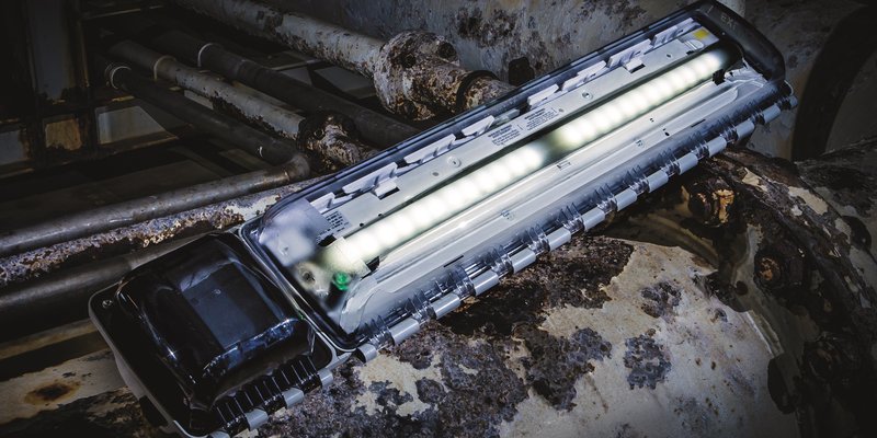
Central battery systems as emergency lighting systems offer secure protection in the event of a power supply failure
Sensing nonsense: When appearances are deceptive
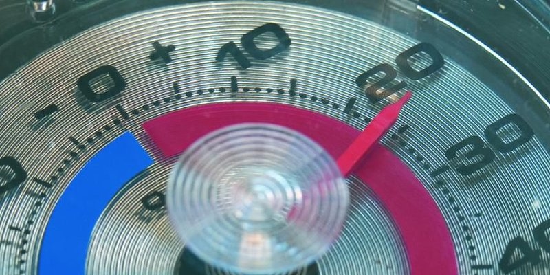
Process engineering systems are generally controlled by measuring process variables such as temperature, pressure, quantity, fill level or…
Digital support for visual inspections using deep learning

The use of deep learning models offers huge potential for reducing the error rate in visual inspections. Smart object recognition enables…
Lightning and surge protection in intrinsically safe measuring…

According to Directive 1999/92/EC [1], the user or employer are obliged to assess the explosion hazard posed by their system and they must…
Ex assemblies, Part 1

The discussion about Ex assemblies is as old as the EU ATEX Directive, and now dates back almost 20 years
How R. STAHL TRANBERG is Meeting the Digitalization Demands of…
Digitalization and the integration of data and solutions is playing a pivotal role in the shipping and maritime industries today, having a…
The "PTB Ex proficiency testing scheme"

The "PTB Ex proficiency testing scheme" (PTB Ex PTS) is a project that involves developing interlaboratory comparison programmes to assess…
Non-electrical explosion protection
Manufacturers and users must acquire knowledge on the subject of non-electrical explosion protection, in order to assess the application,…
Certification in South Africa

Certification in South Africa has certain key differences from international certification, e.g. IECEx or ATEX
Global conformity assessment using the IECEx system
![[Translate to Englisch:]](/fileadmin/_processed_/c/e/csm_Einstiegsbild_IECEx_Paragraf_38414b50d0.jpg "[Translate to Englisch:]")
IEC Technical Committee (TC) 31, tasked with developing a global conformity assessment system for explosion-protected products
A mine of experience in industry
![[Translate to Englisch:]](/fileadmin/_processed_/f/f/csm_Einstiegsbild_e_tech_IEC_6270d7c66a.jpg "[Translate to Englisch:]")
He takes over from Thorsten Arnhold, who chaired the System for the past six years
Conformity assessment in the USA
In contrast to the international IEC/IECEx community and the European Union, the conformity assessment landscape in the USA is very…
25 Years of the Zone System in the USA
In the area of explosion protection, the publication of Article 505 in the 1996 National Electrical Code (NEC®) was seen as a giant step…
An Ex-citing future with hydrogen
![[Translate to Englisch:]](/fileadmin/_processed_/0/1/csm_shutterstock_1644506059_7d60f29da8.jpg "[Translate to Englisch:]")
Aside from a few exceptions based on the effect of gravitation and radioactivity, hydrogen is the source of most primary energy that makes…
Certification of Ex products
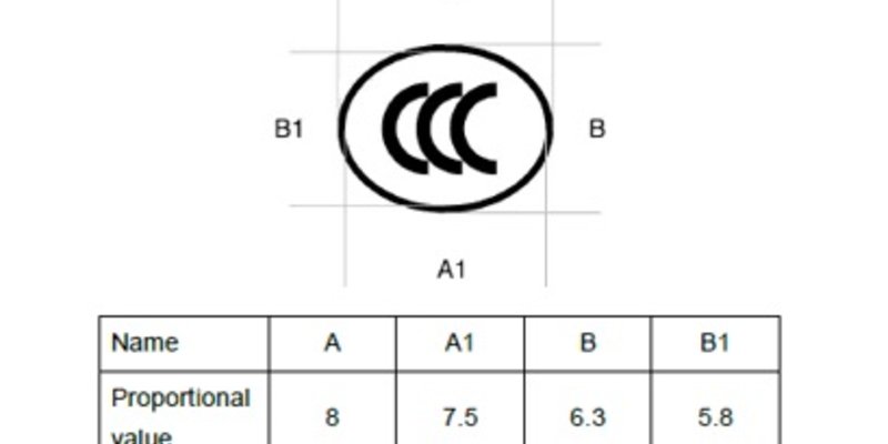
Since 1st October 2019, new CCC certification rules have been in place for Ex products sold in China