Power that never ends
DOI: 10.60048/exm20_07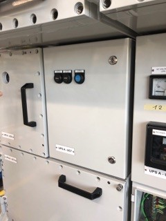
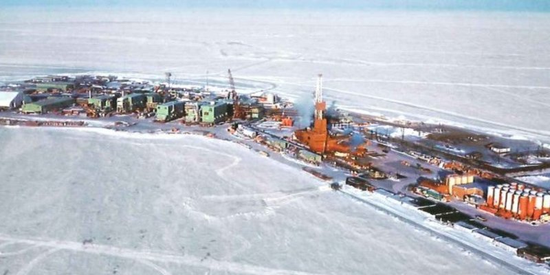
Offshore platforms providing crude oil and natural gas require sufficient electrical energy in a continuous supply in order to guarantee their operational and safety functions. Even a short power supply failure due to a surge caused by lightning strikes would be enough to cause severe safety issues on board and around the facility. For instance, if the signal lighting fails, this could have significant consequences for nearby sea and air traffic.
This general assessment changes very little when considering the power supply to unmanned offshore platforms. Of course, here there is no need for most functions dedicated to guaranteeing the safety of a permanent crew; however, new safety-critical functions that are required for remote control of the platform take their place.

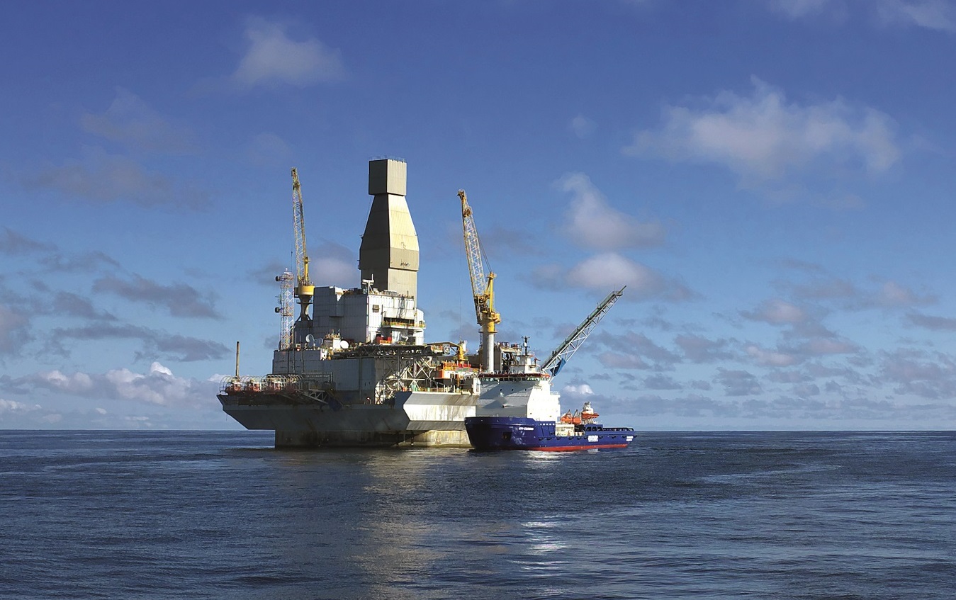
Due in part to the continuously growing cost pressure on the global oil and gas industry, and partly to the increasing lack of affordable, qualified employees, a few years ago it became common practice to move significant proportions of upstream activities, i.e. raw material extraction, to unmanned offshore platforms. Extraction facilities of this type are relatively small structures that are firmly anchored in steel or concrete foundations near the coast. Since there is no permanent crew, all functions of these facilities must be controlled in real time from a remote control centre located either on the mainland or on another platform.
Cost-effective construction and operation of unmanned, remote-controlled extraction facilities only became a possibility in recent years thanks to significant advances in digitalisation. Suitable sensors and actuators, control and network solutions, and stable and reliable communication pathways between the platform and the control centre many kilometres away are all required in order to guarantee efficient, safe production. Malfunctions on unmanned facilities need to be avoided just as strictly as those on conventional manned platforms for both commercial and safety-related reasons. Some potential causes of errors that could lead to malfunctions are the same, while others are different. While the likelihood of human operating errors decreases for unmanned platforms, the probability of accidental or deliberate malfunctions during data transmission increases (cybersecurity and information security risks).
A stable, reliable power supply is therefore essential to the safe operation of an offshore platform. Since the particular conditions of offshore operation mean that primary power supply failures must be expected, uninterruptible power supplies (UPSs) are used in order to maintain essential functions in the event of a power failure until the main power supply can be restored.
ADNOC Offshore, based in the United Arab Emirates, operates a number of unmanned platforms in the Persian Gulf.
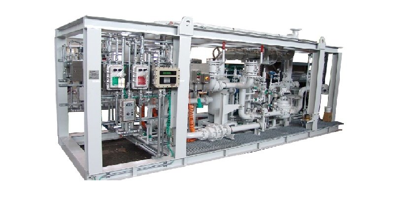
In 2018, they contracted R. STAHL to construct four USPs. The customer's requirements regarding the intended usage conditions, functional safety and capacity posed tricky challenges for the explosion protection specialist's engineering, logistics and production departments.
Unmanned platforms tend to make things easier when it comes to the general safety requirements on board. It is clear to see that the lack of a permanent crew means that some significant safety precautions can be omitted, safe in the knowledge that the offshore facility has comprehensive digital monitoring and extremely high system reliability. Of course, this simplification comes at a cost – there is no quick manual means of intervention on the platform.

Although errors can, in most cases, be rectified by accessing the process remotely, a power supply failure requires specialists to be deployed on-site, supported by a mobile power supply unit. The time between transmission of the message about the power supply failure and the arrival of the damage control team with a mobile power supply needs to be bridged in order to maintain the most important safety-critical system functions such as fire and gas protection, and navigation lighting, at the very least. It was assumed that it would take around three hours to transport the maintenance personnel by helicopter – but transporting an emergency generator by ship is even more time-sensitive.

The challenge to be overcome in this case was to supply a UPS unit that could provide at least ten hours of power. Due to the potential presence of hazardous explosive atmospheres, the entire facility had to be designed with explosion protection suitable for use in Zone 1.
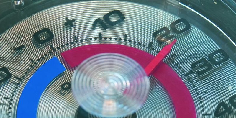
Last but not least, the climatic conditions typical of the Middle East also posed a significant challenge.
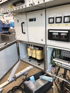
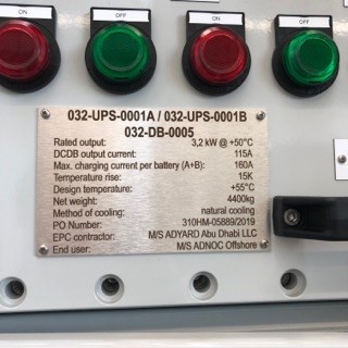
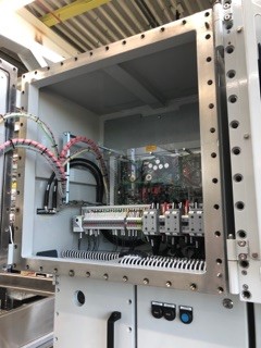
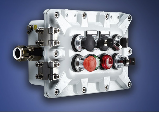
The UPS system essentially comprises two battery containers with a total capacity of 2 x 1650 = 3300 Ah, two parallel charging and monitoring units, and the power distribution board, which connects the UPS to a total of 24 DC outputs. The explosion protection concept is based on a combination of a flameproof enclosure (db) and increased safety (eb). Individual components are protected using encapsulation (mb). The use of the Cubex enclosure, which is almost rectangular in shape, enables a particularly compact construction design. Due to the strict requirements regarding the functional reliability of the facility, the specialists opted for a redundant structure made up of two parallel charging units. These charging units, which are housed in two distinct, flameproof enclosures, are in turn made up of two separate charging modules. Each charging unit is capable of providing 100% of the required charging power. This creates 2 x 100% redundancy. In normal operation, both charging units supply the load evenly (current sharing).
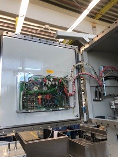
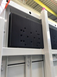
Considering the high temperatures present at the operating location, one significant challenge was to protect the power electronics in the charging modules, based on IGBTs, against unwanted heat. The characteristics of the flameproof enclosure mean that conventional methods of control cabinet climate control are not suitable for use in this case. Using a simplified heating network method, a thermally optimal arrangement of the charging modules was determined. In each case, the power electronics are connected directly to an aluminium plate, which dissipates enough heat from the interior to the heat sinks attached to the outside of the enclosure. For thermal decoupling, one charging module is attached to the door and the other is attached to the rear wall of the enclosure. The aluminium plates are integrated directly into the wall of the flameproof enclosure, like an inspection window; during this process, it is ensured that the material combination of aluminium and stainless steel, which is susceptible to corrosion, is safely separated.
The use of the patented cold plate technology enabled the integratable permissible power dissipation relative to the enclosure size to be increased by a factor of five.
Even at an ambient temperature of 55 °C, the interior temperature of the flameproof enclosure does not exceed 70 °C. This significantly increases the service life of the power electronics. Even the maximum temperature of the external surfaces does not exceed 58 °C.
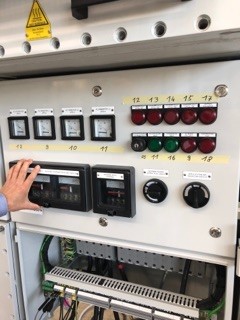
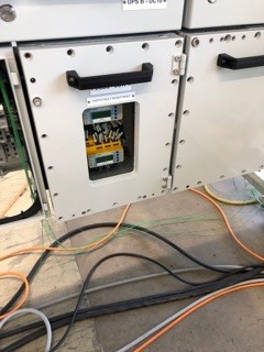
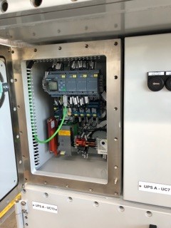
The operating and charging regime is controlled individually for each charging unit using PLCs that are specifically provided for energy management. These PLCs are also responsible for monitoring the charging states and transmitting the operating conditions to a superordinate control system via the Modbus TCP/IP protocol. In addition, registered error conditions are stored in an error memory, the status of which is displayed on-site by a small control system with an LCD display.

If one of the four charging modules fails, a message is transmitted to the control centre for the platform (RTU = remote termination unit). However, as three-quarters of the charging power is still available in this situation, the system availability is significantly increased in comparison to a conventional 2 x 100% redundancy, safely providing 2 x 2 x 100% of the load.
In the RTU, the messages about critical system states are collected, stored and transmitted to the control centre on the mainland (by remote data transmission, fibre optic connections?).
The current battery status is monitored directly by the "Ex UPS Guard" assembly developed by R. STAHL, with a direct connection from the battery containers to the charging units. If critical error conditions such as deep discharge or overvoltages occur, a message is sent to the RTU and, if necessary, the battery is disconnected.
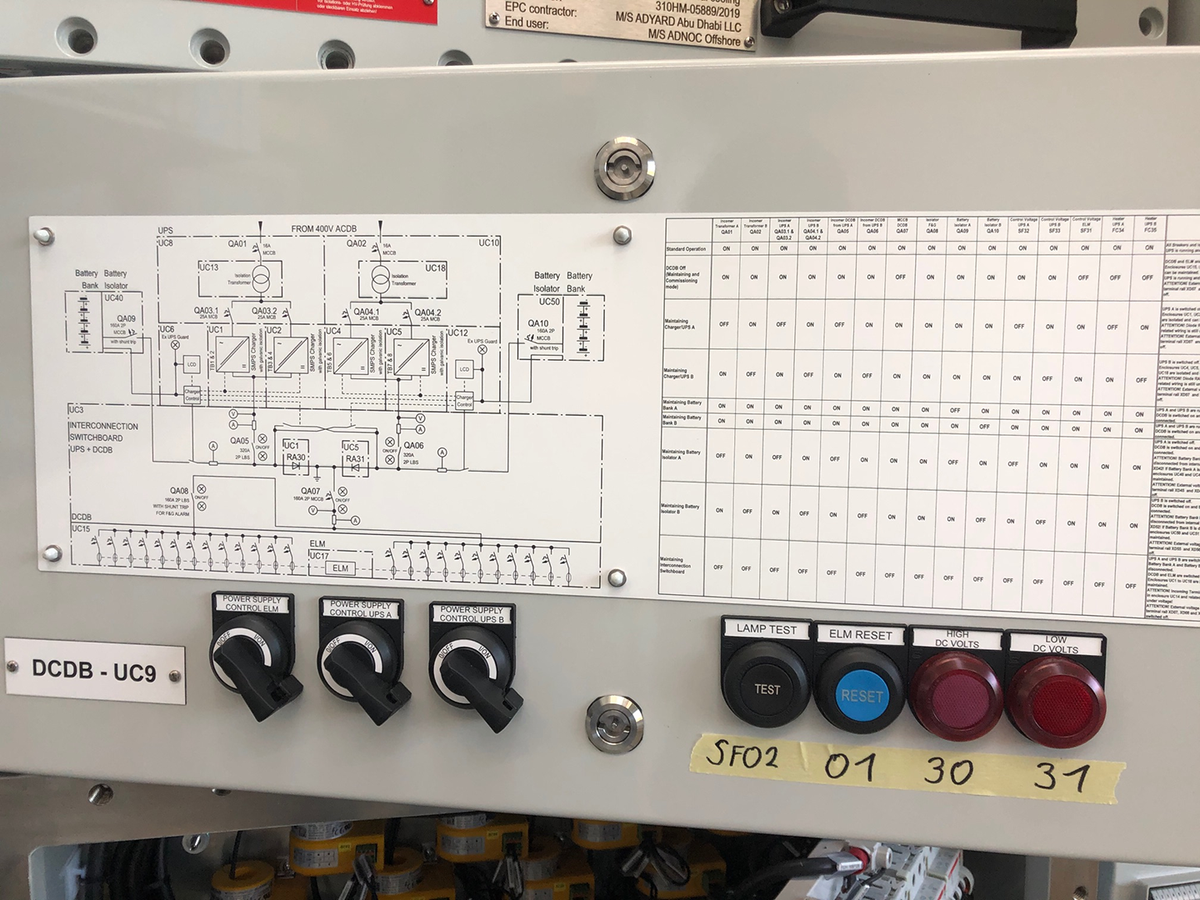
The electrical energy provided in normal or emergency power operation is distributed via the DC distribution board to the corresponding consumer outputs.
Two coupled diodes positioned on the input side ensure that all batteries can be charged by one of the charging units in the event that the other charging unit fails. A switch-off device is positioned in front of the DC outputs – when battery operation is initiated after a power supply failure, this device switches off all DC supplies for non-essential safety-related functions with a time delay. This ensures that there are always sufficient energy reserves for key safety functions such as navigation lighting and the fire and gas system.
All DC outputs are checked using current transformers. The current transformers are combined with a monitoring device for leakage currents.
Even for an experienced system provider like R. STAHL, the concept design, engineering and construction of the UPS system posed a particular challenge, which was overcome through close collaboration with the customer.
Furthermore, R. STAHL provided additional important services such as the organisation and implementation of type tests as per IEC 62040-5-1 and -5-3 in collaboration with the Intertec test body, as well as training for the intended maintenance personnel using the facility documentation. Due to travel restrictions in place because of the COVID-19 pandemic, this training had to take place as an online event, which was considered a great success by all participants.
More Article
Investigation of hydrogen generation in subsea umbilicals

In a growing number of cases, a build-up of hydrogen has been detected in the junction boxes located above the surface of the water, where…
Ex in sight
![[Translate to Englisch:]](/fileadmin/user_upload/magazin/artikel/20_27_Ex_im_Blick/1_Ex_im_Blick_Teaser.jpg "[Translate to Englisch:]")
Incorrect storage of hazardous chemical substances and inadequate surveillance of storage areas all too often result in catastrophic…
The Need for Integrated Project Management
Reducing project management and development time alone has the potential to deliver 15 to 30 percent in cost savings
Static and dynamic material stresses acting on Ex "d" enclosures
Flameproof enclosures must be subjected to certain testing, including of their ability to withstand pressure
PLP NZ celebrating 45 years with R. STAHL

45 years ago, three things came together, R. STAHL, PLP (Electropar Ltd), and the willingness to adopt innovative new hazardous area…
Emergency lighting
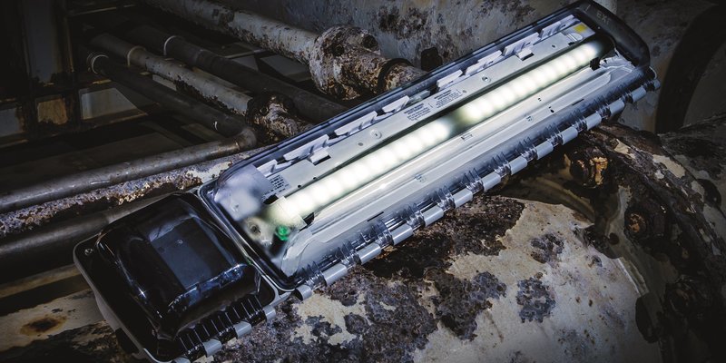
Central battery systems as emergency lighting systems offer secure protection in the event of a power supply failure
Sensing nonsense: When appearances are deceptive
Process engineering systems are generally controlled by measuring process variables such as temperature, pressure, quantity, fill level or…
Digital support for visual inspections using deep learning

The use of deep learning models offers huge potential for reducing the error rate in visual inspections. Smart object recognition enables…
Lightning and surge protection in intrinsically safe measuring…

According to Directive 1999/92/EC [1], the user or employer are obliged to assess the explosion hazard posed by their system and they must…
Ex assemblies, Part 1

The discussion about Ex assemblies is as old as the EU ATEX Directive, and now dates back almost 20 years
How R. STAHL TRANBERG is Meeting the Digitalization Demands of…

Digitalization and the integration of data and solutions is playing a pivotal role in the shipping and maritime industries today, having a…
The "PTB Ex proficiency testing scheme"

The "PTB Ex proficiency testing scheme" (PTB Ex PTS) is a project that involves developing interlaboratory comparison programmes to assess…
Non-electrical explosion protection

Manufacturers and users must acquire knowledge on the subject of non-electrical explosion protection, in order to assess the application,…
Certification in South Africa

Certification in South Africa has certain key differences from international certification, e.g. IECEx or ATEX
Global conformity assessment using the IECEx system
![[Translate to Englisch:]](/fileadmin/_processed_/c/e/csm_Einstiegsbild_IECEx_Paragraf_38414b50d0.jpg "[Translate to Englisch:]")
IEC Technical Committee (TC) 31, tasked with developing a global conformity assessment system for explosion-protected products
A mine of experience in industry
![[Translate to Englisch:]](/fileadmin/_processed_/f/f/csm_Einstiegsbild_e_tech_IEC_6270d7c66a.jpg "[Translate to Englisch:]")
He takes over from Thorsten Arnhold, who chaired the System for the past six years
Conformity assessment in the USA
In contrast to the international IEC/IECEx community and the European Union, the conformity assessment landscape in the USA is very…
25 Years of the Zone System in the USA
In the area of explosion protection, the publication of Article 505 in the 1996 National Electrical Code (NEC®) was seen as a giant step…
An Ex-citing future with hydrogen
![[Translate to Englisch:]](/fileadmin/_processed_/0/1/csm_shutterstock_1644506059_7d60f29da8.jpg "[Translate to Englisch:]")
Aside from a few exceptions based on the effect of gravitation and radioactivity, hydrogen is the source of most primary energy that makes…
Certification of Ex products
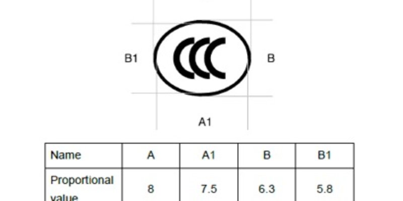
Since 1st October 2019, new CCC certification rules have been in place for Ex products sold in China